Mechanical design (rev A printed, rev B machined)
Status: designed, not built or tested. Every number below comes out of the model and the calculation scripts in caliper/hardware/mechanical/; none of it has been measured on a part yet. Items marked (TVP) are assumptions to verify on the prototype (section 12 collects them).
- Architecture of record: SPEC sections 2.1 and 7. SPEC wins on any disagreement. Section 3 lists where SPEC cannot be built as written and what the model does instead (tagged
DEV-ninparams.py). - Model:
params.pyholds every dimension;models.pybuilds exact B-rep solids with build123d 0.13 (OpenCascade).run_all.shregenerates the STLs, STEPs, drawings, clash report, calculations and renders in about two minutes (WSL, the dial-me-spinner venv). - Calculations:
calcs.pyprints everything quoted here intocalcs_output.txt. The moving jaw was also checked with FEA (fea_jaw.py, linear tets, theprint-stresssolver):fea_jaw_output.txt. - Interference check:
clash_check.pyintersects the B-rep solids exactly (804 pairs) →clash_report.txt. The slider board is still a placeholder envelope built from SPEC 2.1 (board_envelope.py) until the layout exists.
1. Concept
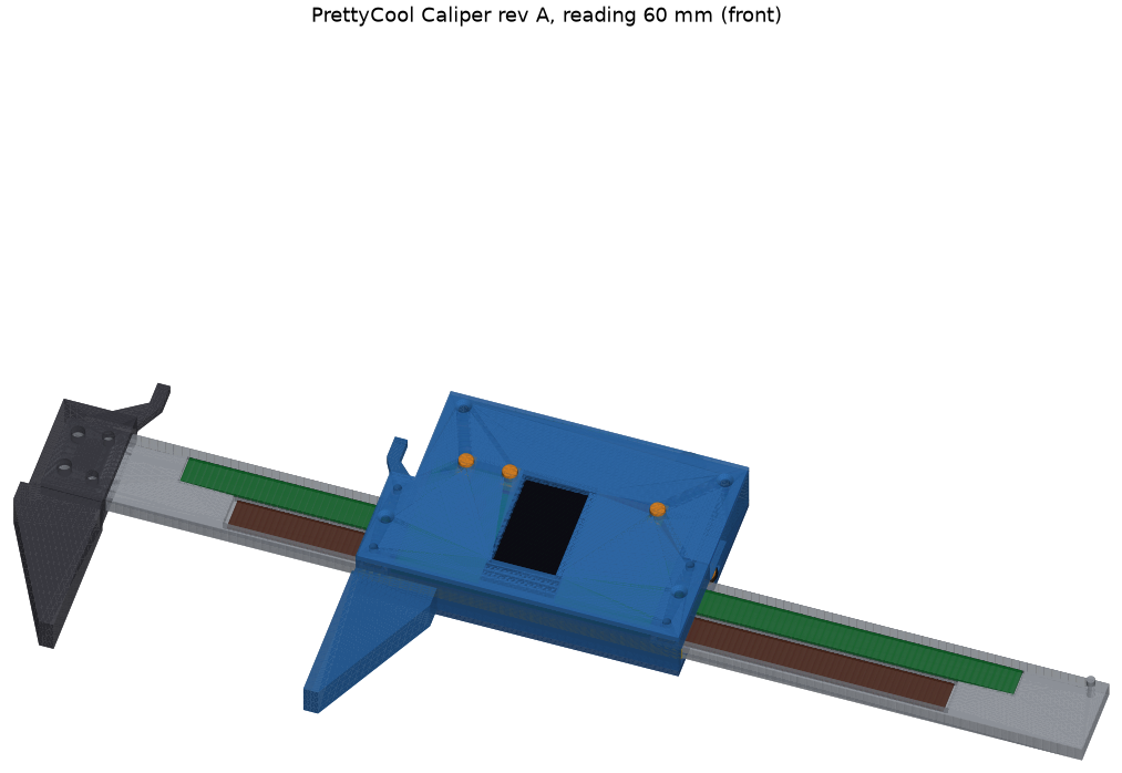 | 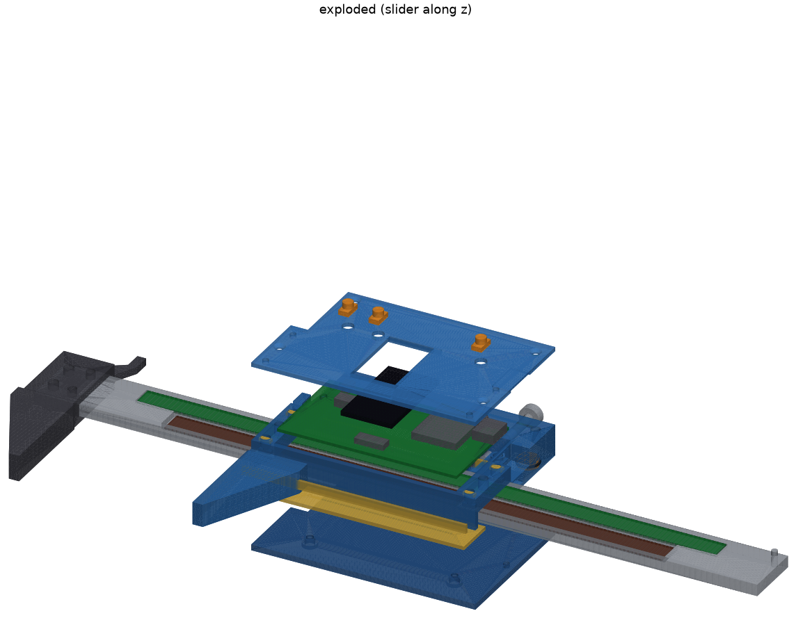 |
| Assembly at reading 60 mm | Exploded along z: front shell and caps up, back cover, back gib and battery down |
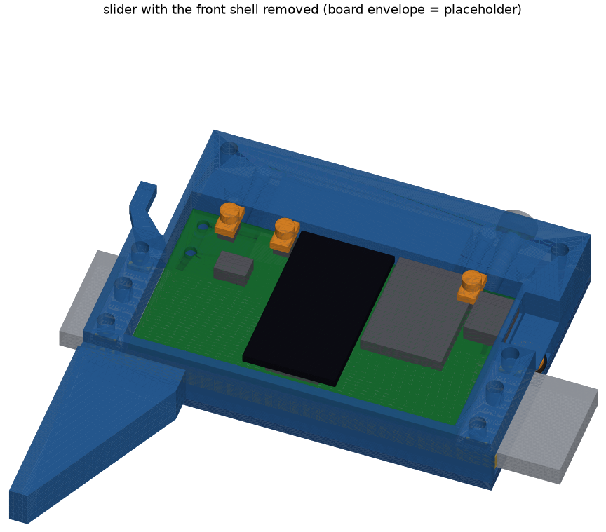 | 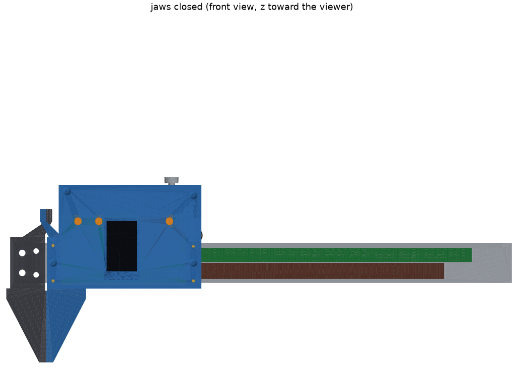 |
| Slider with the front shell removed (placeholder board envelope) | Jaws closed (R = 0), seen from the front: the inside jaws cross above the beam |
Coordinates used everywhere (model, drawings, this page): x along the beam, x = 0 at the fixed jaw's measuring face; y across it, y = 0 at the beam's lower (jaw-side) reference edge, which is also the slider board's y (SPEC 2.1); z through it, z = 0 at the beam's front face, the back face at z = −4. The slider is built in its own frame u = x − R, where R is the reading.
| Part | Rev A | Rev B |
|---|---|---|
| Beam | ground flat stock 20 × 4 × 250, O1 (preferred) or 1.4301, two pockets and five holes | same, to drawing PCC-M-02 |
| Fixed jaw | printed PA-CF block that clamps the beam end: 2 × M3 + 2 × Ø3 dowels | 6061-T6 or tool steel |
| Slider body | printed PETG or (better) PA-CF; straddles the beam, outside and inside moving jaws integral | CNC 6061-T6, drawing PCC-M-01 |
| Front shell | printed lid, display window + bezel ribs, button holes, hex-key access to the gap screws | printed or 6061 |
| Back cover | printed; battery door, the two back-gib plungers | printed or 6061 |
| Gibs | brass C360: back gib, Y gib, reference strip, 4 front pads | same |
| Depth rod | omitted in rev A (section 7) | open |
Key numbers (from params.py and calcs_output.txt):
| Quantity | Value |
|---|---|
| Housing envelope | 77.5 × 52.0 × 16.0 mm (SPEC 7: ≤ 78 × 52 × 16), the thumb-roller rim 0.6 mm proud of the right end |
| Travel | 0–150 mm, hard stop at 151 (a Ø2 pin in the beam) |
| Capacitive gap | 0.150 nominal; ±0.044 RSS after the per-unit setting |
| AS5311 gap | 0.300 nominal; ±0.048 RSS after the per-unit shim and setting, but ±0.13 worst case, which is outside the SPEC window of ±0.10 |
| Moving-jaw flex at the tip, 5 N | PETG 21 µm, PA-CF 8.6 µm, 6061 0.4 µm (beam theory); FEA 20 / 8.2 / 0.5 µm |
| Masses (solid) | beam 125 g, slider body 23 g PETG / 50 g 6061, back gib 9 g |
2. Stack-up and section
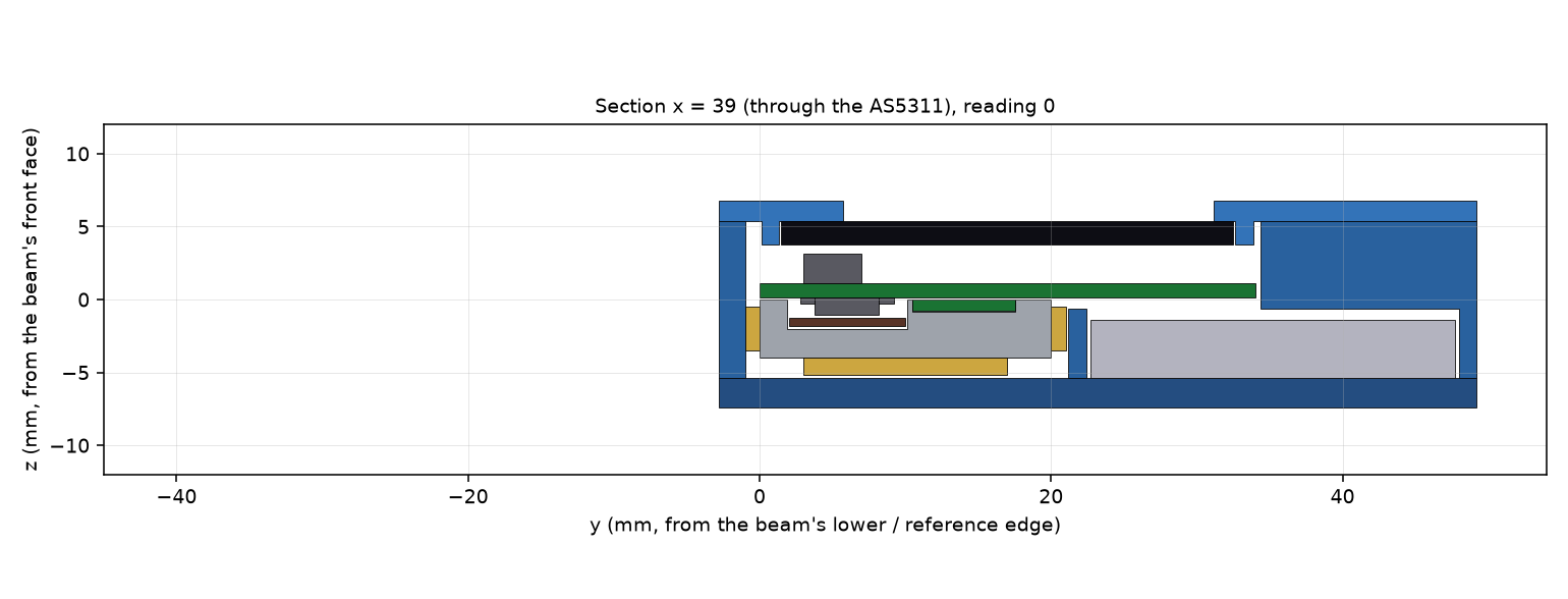
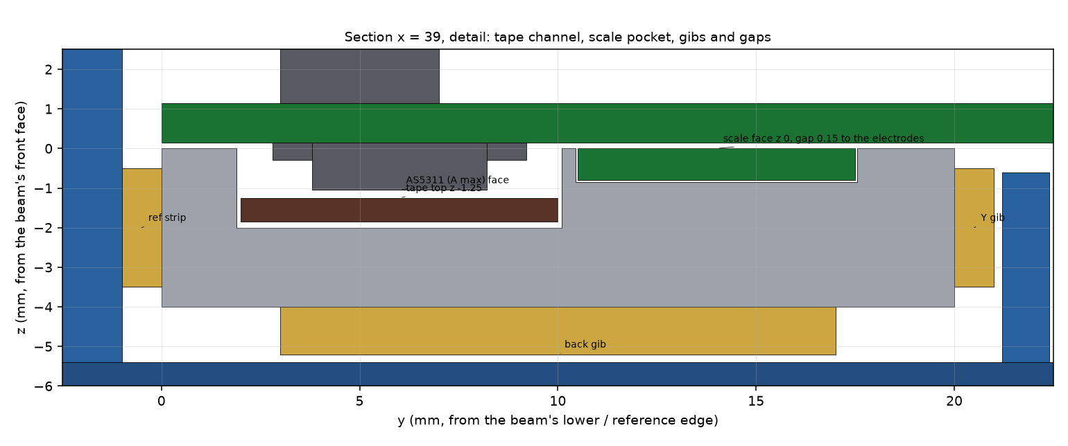
Section at x = 39 (through the AS5311) at R = 0, from render.py (exact section() of the solids).
| z (mm) | Item | Source |
|---|---|---|
| +6.8 | front-shell top (button caps +0.6 above) | Z_LID |
| +5.4 | front-shell underside = body front face; display glass glued here, 1.6 thick to +3.8 | display 17.6 × 31.0 × 1.6 |
| +1.15 | board top; tallest top part ESP32-S3-MINI-1 2.55 → +3.70 | SPEC 2.1 |
| +0.15 | board bottom = capacitive electrodes | SPEC 7 cap gap 0.15 |
| 0.00 | beam front face; scale PCB face flush (pocket 0.85 = 0.80 PCB + 0.05 467MP) | SPEC 7 |
| −0.95 | AS5311 package face (A nominal 1.10; JEDEC MO-153 range 0.85–1.20) | |
| −1.25 | tape face: 0.30 below the AS5311 | SPEC 4.1 |
| −2.00 | tape-channel floor (0.60 tape + 0.05 adhesive + 0.10 Kapton shim for a nominal package; 0–0.35 per unit) | DEV-2 |
| −4.00 | beam back face; back gib 1.2 thick to −5.2 | |
| −5.4 | body back face = back cover inside face | |
| −7.4 / −8.6 | back cover outside / plunger bosses |
Across the beam (y): reference strip y −1…0 under the lower edge, front-pad lands y 0…1.9 and 17.55…20, tape channel y 1.9…10.1 (8.2 wide, the AS5311's 6.4 mm lead span runs inside it with 0.9 each side), a 0.35 land, scale pocket y 10.45…17.55, Y gib y 20…21 on the upper edge.
The board sits 0.15 above the beam over its whole lower band, so nothing on the board bottom may cross the beam except inside the tape channel (≤ 1.30 tall there). The housing therefore cannot touch the beam front face under the board: it locates on the beam only at its two end towers (u 0.5…6.4 and 70.4…78), beyond the board's ends.
3. Deviations from SPEC (and SPEC issues found)
| # | SPEC says | Problem | Model does |
|---|---|---|---|
| DEV-1 | tape 10 mm wide, centred y = 6 | band y 1…11 overlaps the scale band y 10.5…17.5 by 0.5 mm | tape slit to 8.0 mm, centre kept at y 6.0, channel y 1.9…10.1 |
| DEV-2 | tape and scale both flush ±0.05 with the beam face | the AS5311 (0.85–1.20 tall) and the electrodes are on the same flat board bottom; a 0.30 magnetic gap and a 0.15 capacitive gap need the tape face 1.25 below the scale face | the tape lies in a 2.00 mm-deep channel; the AS5311 runs inside it. 2.00 mm of steel remains under the channel. The depth is chosen so the tallest package (A 1.20) gets 0.30 with no shim (section 6) |
| DEV-3 | M2 holes at (3, 3), (59, 3), (3, 31), (59, 31) | (3, 3) and (59, 3) are over the beam with 0.15 mm under the board: no boss, nut or head fits | 3 holes: (3, 24.5), (3, 31), (59, 32.6), bosses rise from the body in the band clear of the beam. USB-C, MINI-1 and the battery leave no 4th spot (TVP with the layout) |
| DEV-4 | USB-C at y ≈ 26 | the cable overmold (12.4 × 6.6) at y 26 clips the beam's upper corner | y 26.5 |
| DEV-5 | HOLD/SEND at x ≈ 20 | its cap would cut into the display glass (glass x 21.2…38.8) | x 18.5 |
| — | display "about 30.0 × 13.5 × 1.5 glass, 24.9 × 14.9 active" (task brief) | 13.5 is narrower than the 14.9 active area | vendor outline 17.60 × 31.00 × 1.60, active 14.86 × 24.91 (BuyDisplay / Chance Display 1.14" 135×240 drawings); portrait, centred at board (30, 17) |
| — | MODE at x ≈ 54 in the upper band, MINI-1 with its antenna at the top edge | with the display at x 21–39, the module (15.4 wide) can only go at x ≈ 39–55, which is where MODE is | not resolved: board_envelope.py reports U_MCU × SW_MODE, and the clash check reports the MODE cap touching the USB-C. The layout has to move one of them |
4. How the slider locates on the beam
Five brass contacts and three spring loads:
- Y (across the beam): the brass reference strip (1.0 × 3 × 77.5, glued into the lower rail) rides on the beam's lower edge, the reference edge E (straight 0.01/150 on the rev B drawing). Two Y plungers (u 16 and 58.5) push the brass Y gib onto the upper edge, which pulls the strip up onto edge E. Each plunger is an M2 set screw in a heat-set insert at the top face, a Ø1.8 spring and a Ø2 steel pin down a 28 mm bore (TVP). The 5 N measuring force at the jaw tip (y −37) and the equal drive force from the thumb (y +20 at the roller, up to y +35 on the end face) form a couple. Keeping the strip seated needs ≥ 3.5 N each with the roller drive and ≥ 4.4 N for a push on the end face (calcs §2). The design value is 6 N each.
- Z (through the beam), position: four brass front pads (4 × 1.5 or 2.0 × 1.0) ride on the beam's front lands (y 0.2…1.7 and 17.8…19.8) at the two towers. Each sits under an M2 set screw in an insert, reached through Ø2.0 holes in the front shell. These four screws set both sensor gaps.
- Z, preload: the brass back gib (1.2 × 14 × 64) is pushed onto the back face by two spring plungers in the back cover (u 14 and 64, y 10). Design 4 N each (calcs §3): a button press (2.5 N at y 31) needs ≥ 1.7 N; a 5 N grip on the battery bay would need 6 N, so a hard squeeze at the top edge (> 3.3 N at y 40) lifts the lower pads off the beam while it lasts. The gaps then open; they never close.
- Locking screw: an M3 knurled thumb screw from the top face (u 63) clamps the Y gib.
- Thumb roller: a printed Ø7 hub with an NBR O-ring (ID 6 × 0.8) on a Ø2 pin, rolling on the beam's upper edge with 0.15 mm squeeze, rim 0.6 mm proud of the right end face below the USB-C.
- Sliding force: 2 × (8 + 12 N) × μ 0.2 ≈ 8.0 N with these preloads, against 2–5 N for a commercial caliper. That is too stiff. The Y preload can't go much below 4.5 N each (see above), so the realistic levers are a lower μ (oiled brass on ground steel, 0.12) or a lower back preload.
- Known defect: the back cover can't hold the back-gib preload. The two back plungers push the cover away from the body with 8 N. Behind the beam (y −1…21.2) there is no body material, and the cover's only screws are at y 44. So the cover works as a 34 mm cantilever, and calcs §3 gives 0.6–1.1 mm of bending in PA-CF (1.4–2.7 mm in PETG). That uses up the plungers' ~1 mm working travel, so the preload that seats the front pads, and so holds both gaps, is not there. Not fixed in the model yet. Options: extend the cover over the moving jaw's root (u 0.5…20, y < −2.8) and screw it there, which deals with the left plunger only. Add a cover screw at about (67.5, 23.5) on the right, between the lock bore and the roller slot. Or move the back preload to a strap or clip that wraps the lower rail.
The jaw is coplanar with the beam within 0.5 mm in z (jaw centre z −1.5, beam centre −2), so the measuring force puts almost no twist into the guide.
5. Gap stack-up
From calcs.py §5 and §6:
| Gap | Open-loop (no per-unit work) | After the per-unit setting (section 6) | Window |
|---|---|---|---|
| capacitive 0.15 | ±0.134 RSS, ±0.25 worst: can't be built open-loop (scale FR4 ±0.08, printed bosses ±0.10) | ±0.044 RSS, ±0.10 worst | experimental; touching is the only hard limit |
| AS5311 0.30 | ±0.190 RSS: outside (package height alone is ±0.175) | ±0.048 RSS, but ±0.13 worst case, outside | 0.20–0.40 (SPEC 4.1) |
After the setting, the AS5311 gap is about 2× inside the window at RSS. The worst case is outside it, though, so tolerances alone don't guarantee the gap. Each unit has to pass the firmware field check (section 6, step 5). The biggest remaining terms are the board height as set (board bow ±0.03, PETG creep ±0.02, screw resolution ±0.011) and the tape thickness along its length (±0.02, TVP).
The ±0.03 board-bow term is an assumption, and it is the weakest one. The board is held only by bosses at y ≥ 24.5. Its lower band (electrodes y 10.6…17.5, AS5311 at y 6) overhangs the bosses by 7–24 mm with nothing under it. ±0.03 is a tenth of the IPC-6012 class 2 bow-and-twist limit (0.75 %): at that limit, the 40 mm electrode strip could be 0.30 out, twice the capacitive gap. Rev A therefore needs a flatness check on every slider board (step 1 below). The proper fix is a board datum near the sensors, for example tabs at the board's ends that a tower pulls up against a ledge. That needs the board outline changed, so it is a contract item.
6. Setting the gaps (assembly procedure)
- Before fitting the board: micrometer the board thickness beside the AS5311 and the board + AS5311 stack, which gives the seated package height A to ±0.005. Check the board's lower band (y 0…20) on a surface plate and reject a board that is more than 0.03 out of flat over the electrode strip. Section 5 explains why.
- Bond the scale and the tape with 3M 467MP. Depth-gauge the tape face and the scale face below the beam face D at 5 points along the travel. Predict the AS5311 gap = 0.15 + 2.00 − 0.05 − tape − shim − A, and lay 0–0.35 mm of Kapton shim (0.025 steps) under the tape until it predicts 0.30. Unshimmed, the tallest package (A max 1.20) gets 0.30. A shim raises the tape, which only closes the gap, so every shorter package can be brought to 0.30 (nominal A 1.10 needs 0.10, A min 0.85 needs 0.35). The first version of the channel (1.90 deep) got this the wrong way round: at A max it gave 0.20 with no shim, and no shim could open that gap.
- Assemble the slider on the beam with the four front-pad set screws backed off and the back plungers set to 4 N. The tower undersides then rest 0.10 lower and the board bottom sits at about +0.05, still clear of the scale.
- Raise to 0.15: with the front shell off, put a dial indicator (2 µm) on a base standing on the beam face beyond the slider. Read the board top at three points over the electrodes, then turn the four set screws (M2 × 0.4: 0.1 mm = 90°) until board bottom = indicator − board thickness = 0.150 ± 0.01 at all three. Lock with Loctite 222.
- Check in firmware at R = 0, 75 and 150: AS5311 MagINCn and MagDECn both high (field in range), SSI status OCF set, COF/LIN clear. The capacitive RX amplitude should vary by less than ±30 %. Record everything in the bring-up log.
7. Parts, print settings and orientation
Bambu P2S, 0.4 mm nozzle, 0.20 mm layers, textured PEI plate. PA-CF needs the hardened nozzle and filament dried at 80 °C for 8 h. Every printed part was checked with the bambu-p2s printability check (printcheck.py) on the exported print-pose STLs. That was the build run; the review changed no printed part and did not run it again:
| Part | File | Material | Pose | Settings | Printability |
|---|---|---|---|---|---|
| Slider body | stl/slider_body.stl | PA-CF (PAHT-CF); PETG for fit trials | back face down | 6 walls, 40 % gyroid, solid jaws (≥ 6 walls fill them) | 22 mm bridges over the beam channel at the towers (OK). Supports needed under the moving inside jaw (14.6 mm overhang) and the roller-slot roof (7 mm): paint-on supports |
| Fixed jaw | stl/fixed_jaw.stl | PA-CF | back face down | 6 walls, 60 % infill | supports needed under the fixed inside jaw (14.4 mm); the 20 mm beam-slot roof flags as a 5.6 mm cantilever (bridgeable) |
| Front shell | stl/front_shell.stl | PETG | top face down (textured) | 4 walls, 100 % | PASS |
| Back cover | stl/back_cover.stl | PETG | inside face down | 4 walls, 100 % | PASS |
| Button cap × 3 | stl/button_cap.stl | PETG | flange down | 100 % | PASS |
| Thumb roller | stl/thumb_roller.stl | PETG | flat | 100 % | PASS |
Clearances: sliding parts get 0.15–0.20 per side (CLR_SLIDE); the brass gibs and pads float in 0.10–0.15 pockets; heat-set inserts M2 × 3 in Ø3.2 holes, M3 × 4 in Ø4.0. The STEP of every part is in step/, in assembly pose, plus step/caliper_assembly.step (25 named solids at R = 0).
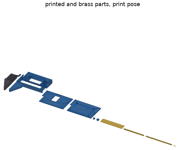
Depth rod: omitted in rev A. A depth rod needs a slot along the beam's back face, and the back face here carries the back gib, whose preload holds both sensor gaps. A rod would also need a bearing in the slider's right tower, which already holds the roller, the USB-C relief and two gap screws. Rev B can add a 1.5 × 4 rod in a back-face groove at y 2…6 (under the tape channel, where 2.0 mm of steel remains, so a groove would leave little), guided by the back cover.
8. Calculation results (summary)
Jaw deflection (calcs §1, FEA in fea_jaw_output.txt). The jaw is 7.8 thick, 20 wide to y −8, tapering to 3.5 at the tip y −40. Printed back face down, so it bends in the layer plane. Interlayer stress is 0.14 MPa (FEA), so strength is not the issue; stiffness is.
| Body | at the tip contact (y −37), 5 N | per N | 2–8 N thumb spread |
|---|---|---|---|
| PETG | 21.4 µm (FEA 15.7 / 0.85 = 18.5) | 4.3 µm/N | 26 µm |
| PA-CF | 8.6 µm (FEA 7.4) | 1.7 µm/N | 10 µm |
| 6061-T6 | 0.4 µm | 0.09 µm/N | 0.5 µm |
At mid-jaw (y −20) every material is under 3 µm. The first jaw drawn (6 thick, 16 root) flexed 36 µm in PETG under FEA, which is why the jaw grew to 7.8 × 20. The fixed jaw (PA-CF) adds about the same again.
Thermal (calcs §4, error after zeroing, per 10 K): PETG body on O1 9.4 µm, PA-CF on O1 5.2 µm, 6061 on O1 4.2 µm. A 1.4301 beam adds 0.7 µm/K at 150 mm against steel workpieces. The scale term is why O1 is the preferred beam material.
Preloads and sliding force: section 4.
9. Rev B machining
drawings/slider_body_b.pdf(PCC-M-01) andstep/slider_body_b.step: the body in 6061-T6, stress-relieved plate, clear anodise with the channel and jaw face masked. Tapped M2 × 0.4 and M3 holes replace the inserts. Datums: A = jaw measuring face, B = channel lower face (reference-strip seat), C = tower underside. The gib and lock bores are at ±0.02 from A, the front-pad screw holes ±0.02 from B, and the channel is 22.20 +0.02/0 × 5.50 +0.02/0.drawings/beam_pockets.pdf(PCC-M-02) andstep/beam_pockets.step: rough both pockets and all holes 0.2 under, harden O1 to 58–60 HRC (1.4301: stress-relieve only), grind face D and edge E, and only then finish the pockets from D (hard O1: carbide hard-milling or EDM) and the holes (ream 1.4301; jig-grind or wire-EDM hard O1). The first version finished the pockets before the final grind. That grind can take up to 0.05 off D, which would have used up the ±0.02 pocket-depth tolerance. Edge E straight 0.01 over any 150, face D flat 0.01/150, pocket floors parallel to D within 0.01, dowel holes H7 ±0.02.- Jaw faces: flat 0.005 and parallel 0.01, reached by lapping the two jaws together. Close them on a lapping strip (1200-grit on a granite plate is the usual shop practice), with the slider clamped by its locking screw, then check against gauge blocks at three heights.
- Hardened jaw inserts: 6061 wears quickly against steel workpieces and can't hold 0.005 for long. The drawing allows an optional 2.0 mm pocket in each jaw face for a 1.2379/D2 (60 HRC) or carbide insert (2.0 × 6 × 34), bonded with structural epoxy, pinned with 2 × Ø1.5, and ground and lapped in place. The same insert would fix the wear problem on the rev A printed jaws, at the cost of the root stiffness that section 8 shows to be the real limit.
10. Hardware BOM
| Item | Qty | Spec / source |
|---|---|---|
| Beam | 1 | ground flat stock 20 × 4, O1 (1.2510 "gauge plate") or 1.4301, cut to 250, e.g. 500 mm lengths from Hoffmann/Garant, RS or McMaster-Carr (TVP: exact SKU) |
| Magnetic tape | 172 mm | ams AS5000-MS10-H075-100 (1.0 mm pole length / 2.0 mm pole pair for the AS5311). Width and thickness not confirmed; the part number is the one in the brief. Or a generic 2 mm pole-pair magnetic encoder tape, slit to 8.0 mm, ≤ 0.60 thick with backing. A thicker tape needs TAPE_T changed, which deepens the channel |
| Adhesive transfer tape | – | 3M 467MP (0.05) for the tape and the scale |
| Kapton shim | – | 0.025 mm sheet, 0–14 layers under the tape (section 6), bonded with the same 467MP or thin acrylic-adhesive Kapton tape (TVP: the adhesive layers count toward the stack) |
| Brass C360 | – | 1.2 × 14 × 64 (back gib), 1.0 × 3 × 60 (Y gib), 1.0 × 3 × 77.5 (reference strip), 1.0 sheet for 4 pads |
| Heat-set inserts M2 × 3 | 17 | 15 in the body (3 board, 4 lid, 4 pad screws, 2 Y plungers, 2 cover), 2 in the back cover |
| Heat-set insert M3 × 4 | 1 | locking screw |
| M2 set screws, cup point | 8 | 4 × M2 × 4 (front pads), 2 × M2 × 3 (Y plungers), 2 × M2 × 3 (back plungers) |
| Compression springs | 4 | Ø1.8 OD, 4–6 mm free; ~6 N (Y plungers) and ~4 N (back plungers) at 1 mm working deflection (TVP: find a stock part, e.g. Lee Spring LC series) |
| Steel pins | 2 + 1 + 1 | Ø2 × 22 (Y plunger pushers), Ø2 × 6 m6 (stop pin), Ø2 × 6 (roller axle) |
| Dowel pins Ø3 × 12 m6 | 2 | fixed jaw |
| M3 × 12 button head + M3 nut | 2 + 2 | fixed jaw |
| M2 × 4 pan head | 3 | board to body |
| M2 × 6 countersunk | 4 | front shell |
| M2 × 6 low head | 2 | back cover |
| M3 × 30 knurled thumb screw | 1 | locking screw |
| O-ring NBR ID 6.0 × 0.8 | 1 | thumb-roller tyre |
| Epoxy | – | reference strip in the rail; display glass to the front-shell ribs (or B-7000) |
11. Clash check result
From clash_report.txt, with the placeholder board:
- Slider vs beam, fixed jaw, tape, scale and stop pin at R = 0, 75 and 151: all clear. The stop pin meets the right end face at R = 151.0.
- Slider-internal pairs (body, shell, cover, caps, roller, gibs, pads, display, battery, lock screw): all clear. The only intended contact is the O-ring tyre squeezed 0.15 mm on the beam.
- Board vs housing: one clash, the MODE cap against the USB-C receptacle. Both positions come from SPEC, so this is the placement conflict in section 3.
- Gaps: AS5311 to tape 0.300 at nominal A with the nominal 0.10 shim (0.200 at A max with that shim; the per-unit shim brings every package to 0.30); electrodes to scale 0.150. The AS5311 leads sit 0.9 mm inside the channel walls. The assembly models the tape at the nominal-shim height; the shim itself isn't a solid.
When the layout exists: run python3 extract_board_parts.py (it looks in caliper/hardware/kicad/slider/), then python3 clash_check.py.
12. Risks and things to verify
- Holding the 0.3 mm AS5311 gap. It works only with the per-unit measurement and shim in section 6. Even then the gap is ±0.048 RSS but ±0.13 worst case, so the firmware check decides each unit. The open-loop stack is about twice the window. Board bow over the slider and tape thickness along the length are guesses (TVP). If the prototype misses, the fallback is to set the board height for the AS5311 (the primary sensor) and let the capacitive gap float.
- The 0.15 mm capacitive gap sits right where a 1.0 mm FR4 board's bow (IPC 0.75 %) matters. Expect amplitude variation along the travel. It is the experimental sensor.
- Jaw accuracy with a printed body: PETG can't meet ±0.03 at the jaw tip under thumb-force variation (26 µm alone). PA-CF reaches about 10 µm per jaw. Wear of printed measuring faces is unquantified. Rev A accuracy should be judged on PA-CF parts measured near the jaw root.
- Creep: PETG bosses and pad pockets under 4–8 N spring loads will relax (TVP). That changes preload, not position, but it moves the board if a boss creeps. Use PA-CF.
- Spring plungers: 4–6 N from a Ø1.8 spring in 1 mm of travel is stiff for that size (TVP: source a part). Sliding force is 8.0 N at the design preloads, too high (section 4). 5a. Back cover bending under the back-plunger load (section 4): an open defect. As modelled, the back preload is not held.
- Supports are still needed under both inside jaws and the roller-slot roof.
- Thumb roller is only 0.6 mm proud, and it can only be reached across the right end face. Its rim (u 78.6) also puts the slider 0.6 mm over the SPEC 7 length of 78 mm, which includes the roller. Ergonomics are unverified. 7a. The stop pin is pressed in after the slider goes on, so the slider can't come off the beam for service without drilling the pin out. A screwed stop (M2 into a tapped beam hole) would fix it.
- Tape: the ams strip's width and thickness are unconfirmed, and a magnetic (O1) beam under the tape may change the field the AS5311 sees (TVP: check MagINC/MagDEC on both beam materials).
- Board layout conflicts in section 3: the mounting holes, MINI-1 vs MODE, and the MODE cap vs the USB-C.
13. Review record
An adversarial review of this track changed the following. The model and outputs were regenerated afterwards (run_all.sh: 23 tests pass, 12 valid parts, STLs watertight by trimesh):
- Tape channel 1.90 → 2.00 deep, so the shim procedure can correct every package (section 6).
- Yaw preload (calcs §2): it now includes the thumb-drive couple. The minimum went from 2.3 to 3.5–4.4 N each, and the design value is now 6 N, so the sliding force is now 8.0 N.
- AS5311 worst case: it was 0.097 with "0.003 margin", which was wrong because the RSS of the board setting had been added into a worst-case sum. The true worst case is ±0.13, outside the window.
- Open-loop capacitive stack: the board-thickness term came out (the board bottom seats on the bosses).
- Beam drawing PCC-M-02: process order fixed (grind D, then finish the pockets).
- Found, not fixed: the back cover can't carry the back-plunger load (section 4); the slider board's lower band is unsupported (section 5); the roller exceeds 78 mm; the stop pin is not removable.